
By William Pearce
Frank Bernard Halford had been an aircraft engine designer since World War I. In 1923, he established himself as a for-hire consultant to design aircraft engines for established manufacturers. By 1927, Halford had designed a new high-revving aircraft engine with numerous small cylinders and minimal frontal area. Halford’s belief was that a smaller engine running at a faster speed would produce the same power as a larger engine running at a slower speed. The new engine design was a vertical H with four cylinder banks, each with four individual cylinders.

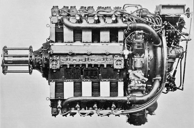
The Napier Rapier I with its intake and exhaust ports mounted on opposite sides of the cylinder, Note the magnetos mounted to the rear of the engine and the external oil line on the crankcase.
Halford showed the design to George Purvis Bulman, the Chief Inspector (of engines) for the British Ministry of Munitions. Bulman was impressed with the design and knew that the British engineering firm D. Napier & Son (Napier) was in search of a new product. Napier’s Lion W-12 aircraft engine was designed 10 years previous, and the company had stopped producing automobiles in 1924. Napier wanted to pursue the development of new aircraft engines but felt that its current in-house design department did not have the needed experience.
Bulman introduced Halford to George Pate, Napier’s Production Chief Engineer. With the blessing of Napier’s board of directors and its chairman, Montague Stanley Napier, Halford was contracted in 1928 to design aircraft engines for Napier. One stipulation was that the engines must fall between a displacement of 404.09 and 718.37 cu in (6.62 and 11.77 L) to not conflict with any of Halford’s projects with other companies. Halford immediately began detailed design work on the H-16 engine, which would eventually be known as the Rapier. The engine is often referred to as the Napier-Halford Rapier.

Rear and front views of the Rapier I. On the left, the upper “Y” intake pipe can be seen behind the spark plug wires. On the right, the intake manifolds can be seen atop the inner side of the cylinder banks, just under the valve rocker housings.
Much of Halford’s previous aircraft engine experience was with air-cooled cylinders, and the 16-cylinder Rapier was no different. An Air-cooled engine was lighter and less complex than a liquid-cooled engine. The Rapier had a two-piece aluminum crankcase that was split horizontally at its center. The left and right crankshafts were supported between the two crankcase halves via five main bearings each. Each one-piece, four-throw crankshaft served one vertical and one inverted bank of cylinders. The crankshafts were phased at 180 degrees (some sources say 90 degrees, and it may be that the Rapier I was so phased and that later engines were at 180 degrees). Power strokes occurred simultaneously for both crankshafts. The connecting rod attached to each crankpin was a master rod with an articulating rod mounted to its end cap. When viewed from the rear, master rods served the upper left and lower right cylinder banks. Spur gears at the front of each crankshaft meshed with a larger gear that was mounted to the propeller shaft, which turned at .390 crankshaft speed. When viewed from the rear, both crankshafts rotated clockwise, and the propeller shaft rotated counterclockwise.
The air-cooled cylinders were made of aluminum heads that were screwed and shrunk onto forged steel barrels. Each cylinder was mounted to the crankcase via four studs. The cylinders had a 6.0 to 1 compression ratio, and each cylinder had a single intake and a single exhaust valve. The intake port was on the inner side of the cylinder, and the exhaust port was on the outer side. The valves for each set of eight upper and lower cylinders were actuated by a single camshaft via pushrods and rockers. Each camshaft was located between its respective set of cylinders (upper and lower). Each cylinder had one spark plug mounted on its outer side and another mounted on its inner side.

The Havilland DH.77 prototype fighter monoplane was initially powered by a Rapier I engine, but a Rapier II was later installed. Note the individual exhaust stacks and the machine gun installed on the side of the aircraft.
An accessory drive case was mounted to the back of the engine. A shaft extending back from the propeller shaft powered the accessory drive gears. Driven from the accessory case were the camshafts, magnetos, supercharger, generator, and various accessories. The engine’s two magnetos were mounted to the rear of the accessory case, and each magneto fired one of the cylinder’s two spark plugs. The single-speed supercharger drew in air through an updraft carburetor and compressed the air and fuel mixture with a centrifugal impeller. The air and fuel mixture exited the top and bottom of the supercharger housing into a Y pipe that distributed the charge to each cylinder via a manifold that ran along the inner side of each cylinder bank. A hand crank or an air starter was used to start the engine.
Napier developed a cowling for the Rapier so that the engine could be installed as a complete package. The cowling was narrow in form and had large upper and lower scoops. For engine cooling, air was ducted between the upper and lower cylinders. Baffles directed the air’s flow through the cylinders’ integral cooling fins and to the outer side of the cylinder banks. The cooling air exited via a cowl flap on each side of the aircraft and behind the engine.

The Rapier II had a revised cylinder with intake and exhaust ports on its outer sides. The supercharger housing was also modified with four outlets serving individual intake manifolds for each cylinder bank. Note the crankcase’s horizontal parting line.
The Napier Rapier I was designated by Napier as the E93. The engine had a 3.5 in (88.9 mm) bore and a 3.5 in (88.9 mm) stroke. Each cylinder displaced 33.7 cu in (.55 L), and the Rapier’s total displacement was 539 cu in (8.83 L). At sea level, the engine had a maximum output of 350 hp (261 kW) at 3,900 rpm and a normal output of 300 hp (224 kW) at 3,500 rpm. The Rapier I was 54 in (1.37 m) long, 21 in (.53 m) wide, and 35 (.90 m) tall. The engine weighed 620 lb (281 kg).
The Rapier I was first run around the start of 1929 and was mainly a developmental engine. The engine was installed in the de Havilland DH.77 (J9771) prototype fighter monoplane, which made its first flight on 11 July 1929. Although the aircraft exhibited good qualities, it was not selected for production. After completing its evaluation, the DH.77 was used to accumulate 100 hours of engine tests until December 1932. A Rapier II engine (see below) was then installed with a modified cowling. Engine development continued until the summer of 1934, when the aircraft was scrapped. The Rapier I was also installed in a Bristol Bulldog TM (K3183) biplane trainer around 1933. The aircraft served as the Rapier I test bed to evaluate the engine and cowling in a wind tunnel and in flight. Bulldog TM (K3183) kept its Rapier powerplant until 1938, when it was used to test another engine.

The Rapier IV was very similar to the Rapier II but with decreased supercharging. The baffles helped direct cooling air through the cylinder’s fins. Note the magneto mounted vertically from the accessory case.
The Rapier II was a development of the Rapier I with the supercharger’s impeller geared at a higher speed to improve the engine’s performance at altitude. New cylinders were used that had the intake and exhaust ports both located on the outer side of the cylinder. The induction system was revised with four outlets from the supercharger that distributed the air and fuel mixture via separate manifolds to each cylinder bank. The accessory case was also updated with the magnetos mounted vertically.
The Rapier II carried the Napier designation E95 and was first run in 1932. At 10,000 ft (3,048 m), the Rapier II had a maximum output of 355 hp (265 kW) at 3,900 rpm and a normal output of 305 hp (227 kW) at 3,500 rpm. The engine was 55.25 in (1.40 m) long, 20.75 in (.53 m) wide, and 35.25 (.90 m) tall. The engine weighed 710 lb (322 kg). As mentioned above, the engine was installed in the DH.77 prototype, which flew in this configuration in early 1933.

The Rapier VI had a revised, magnesium crankcase, a separate gear reduction housing, and used a downdraft carburetor. Otherwise, its structure was similar to that of the Rapier IV.
The Rapier IV was similar to the Rapier II, but it generated maximum power at low altitude due to revised supercharger gearing. At sea level, the Rapier IV had a maximum output of 385 hp (287 kW) at 3,900 rpm and a normal output of 340 hp (254 kW) at 3,500 rpm. The Rapier IV was 52.0 in (1.32 m) long, 21 in (.53 m) wide, and 37.7 in (0.96 m) tall. The engine weighed 726 lb (329 kg). The Rapier IV was first run in 1933, and Napier purchased an Airspeed Courier AS.5C (G-ACNZ) touring aircraft to serve as an engine testbed that same year. The AS.5C with its Rapier IV engine was first flown in June 1934. The aircraft was used as a demonstrator for a few years. By 1937, the engine had been replaced, and the aircraft was sold. Prior to AS.5C’s delivery, two Rapier IV engines were installed in a Saro A.19/1A Cloud (G-ABCJ) amphibious transport. The A.19/1A was the first testbed for the Rapier IV. The aircraft was loaned to Jersey Airways in August 1935 and withdrawn from service in December 1936.
The Rapier V was a further development of the Rapier line. Changes consisted of a magnesium crankcase, a separate updated gear reduction housing, fork-and-blade connecting rods, and an increased compression ratio of 7.0 to 1. The forked rods were in the rear lower cylinders, second from rear upper cylinders, second from front lower cylinders, and front upper cylinders. The induction system was revised to accommodate a downdraft carburetor. The engine was given the Napier designation E100 and was first run in around 1934. At 10,000 ft (3,048 m), the Rapier V had a maximum output of 380 hp (283 kW) at 4,000 rpm and a normal output of 340 hp (254 kW) at 3,650 rpm. Fuel consumption at cruise power was approximately .429 lb/hp/hr (261 g/kW/h) at 240 hp (179 kW) and 3,300 rpm. The Rapier V was 57.37 in (1.46 m) long, 23.37 in (.59 m) wide, and 36.0 in (.91 m) tall. The engine weighed 720 lb (326 kg). Four of the engines were installed in the Short S.20 Mercury (G-ADHJ) seaplane, which first flew on 5 September 1937. These engines were replaced with Rapier VIs in June 1938.

Front and rear views of the Rapier VI. Internally, the engine used fork-and-blade connecting rods and had a cylinder compression ratio of 7.0 to 1. It was the most powerful of the Rapier engines.
The Rapier VI (possibly E106) was similar to the Rapier V, but with decreased supercharging. The Rapier VI had a maximum rating of 395 hp (295 kW) at 4,000 rpm at 6,000 ft (1,829 m); a normal rating of 370 hp (276 kW) at 3,650 rpm at 4,750 ft (1,448 m); and a takeoff rating of 365 hp (272 kW) at 3,500 rpm at sea level. Fuel consumption at cruise power was approximately .412 lb/hp/hr (251 g/kW/h) at 310 hp (231 kW) and 3,500 rpm. The engine was 56.6 in (1.44 m) long, 22.4 in (.57 m) wide, and 36.0 in (.91 m) tall. The Rapier IV weighed 713 lb (313 kg). The engine was first installed in the Fairey Seafox reconnaissance float plane, which made its first flight on 27 May 1936. Early issues were experienced with engine cooling, but ultimately 66 Seafoxes were built, making it the most successful Rapier application. The Seafox was withdrawn from service in 1943. The Rapier IV was also installed in the Blackburn H.S.T.10 transport, the development of which was halted in 1936, before the aircraft was completed.

The Fairey Seafox reconnaissance float plane was powered by the Rapier VI engine, and 66 examples of the aircraft were built.
As previously mentioned, four Rapier VI engines were installed in the Short S.20 Mercury in June 1938. When the S.20 was mounted atop the Short S.21 Maia, the pair formed the Short-Mayo Composite, which was envisioned to provide long-range transport service. After being hoisted aloft by the Short S.21 Maia on 21 July 1938, the S.20 separated and later completed the first commercial, non-stop East-to-West transatlantic flight by a heavier-than-air machine. The Maia-Mercury composite went on to establish a seaplane distance record, covering 6,045 miles (9,728 km) between 6 and 8 October 1938. The Mercury and Maia made several flights until commercial operations were suspended due to World War II.
Cooling the Rapier engine was particularly difficult while the aircraft was on the ground. The uncuffed propellers did not provide sufficient airflow to effectively cool the engine, especially the rear cylinders. This issue was never fully resolved. In the early 1930s, Napier and Halford were working on the development of other aircraft engines, which would ultimately lead to the air-cooled Dagger H-24 and liquid-cooled Sabre H-24. By mid-1935, resources at Napier were wearing thin, and the decision was made to discontinue Rapier development so that efforts could be concentrated on other projects. Rapier production continued until around 1937. One Rapier VI engine was preserved and is on display at the Shuttleworth Collection in Bedfordshire, England.

The Short S.20 Mercury (top) and Short S.21 Maia (bottom) seaplane composite. Although originally fitted with four Rapier V engines, the Mercury had Rapier VIs installed for its service flights. The Maia was powered by four nine-cylinder Bristol Pegasus radial engines.
Sources:
– “The Napier Rapier” Flight (14 March 1935)
– British Piston Aero-Engines and their Aircraft by Alec Lumsden (2003)
– By Precision Into Power by Alan Vessey (2007)
– Boxkite to Jet — the remarkable career of Frank B Halford by Douglas R Taylor (1999)
– Aircraft Engines Volume Two by A. W. Judge (1947)
– Jane’s All the World’s Aircraft 1931 by C. G. Grey (1931)
– Jane’s All the World’s Aircraft 1934 by C. G. Grey (1934)
– Jane’s All the World’s Aircraft 1936 by C. G. Grey (1936)
– Aerosphere 1939 by Glenn D. Angle (1940)
– An Account of Partnership – Industry, Government and the Aero Engine by George Bulman and edited by Mike Neale (2002)
– Aircraft Engines of the World 1941 by Paul H. Wilkinson (1941)
– Bristol Aircraft since 1910 by C. H. Barnes (1964/1994)
– De Havilland Aircraft since 1909 by A. J. Jackson (1987)
– Airspeed Aircraft since 1931 by H. A. Taylor (1970)
– Saunders and Saro Aircraft since 1917 by Peter Jackson (1988)
– Shorts Aircraft since 1900 by C. H. Barnes (1989)
– Fairey Aircraft since 1918 by H. A. Taylor (1974/1988)
– Blackburn Aircraft since 1909 by A. J. Jackson (1968/1989)

Another great summary of an interesting engine. Great work, thanks, DAJEN