The Foundation for Science, Technology and Civilisation (FSTC) announces their new achievement in the history of Islamic clocks. For the first time, the work of Ibn al-Haytham on the water clock (Maqala fi ‘amal al-binkam) is uncovered and edited from two manuscripts. Whilst work is currently undertaken to produce a critical edition of the text in a book that will be published in 2015, we are proud to publish a glimpse of this pioneering work of Ibn al-Haytham’s contribution on mechanical clocks. In this article Professor Salim Al-Hassani, President of FSTC, summarises the text and publishs its draft English translation. In addition, he describes the mechanism of the water clock and produces engineering diagrams as well as a 3D animation video of its working procedure. To verify the technical details of the description of the clock, a mathematical analysis was also carried on. Although rudimentary at this stage, this analysis, in conjunction with the drawings and video animation, should be useful in design replicas or models of this clock. This ground breaking article precedes the full historical editing work which is to be published by Professors Al-Hassani and Mohammed Abattouy in due course.
by Professor Salim Al-Hassani, President of FSTC
This work would have not been achieved had it not been for the assistance of a number of people. Of special mention are: Prof. Mohammed Abattouy for his valuable assistance in editing the manuscript and in historical research, Prof. Hamza Kandor for providing digital copies of the manuscripts, Sara Tahboub for helping with the translation, Dr Stephen Burley for his assistance and advice with the mathematical analysis, and Abdul Kader Jahjah for his assistance with the drawings and interpreting of old Arabic engineering terms. We mention also the financial assistance received from from Zuhair Fayez and Dessert publishers, for which we express our thanks and gratitude.
1. About Ibn al-Haytham’s Life
2. The Manuscript Copies
3. Remarks about the English Translation
4. Description of the Clock
5. Mathematical Analysis of the Clock
6. Discussion and Concluding Remarks
7. The English Translation of Maqala fi ‘amal al-Binkam
8. Details of the Mathematical Analysis
9. References

Imaginary potrait of Ibn al-Haytham (Source)
Abu ‛Ali al-Hasan Ibn al-Haytham (965-1039 CE) was born in Basra, Iraq, around the year 965 CE (354 H). His scientific career began in Basra, but most of it flourished in late 10th and early 11th– centuries Fatimid Cairo, founded in 972 CE. Also known in Europe by the name Alhazen, since the translation of his works into Latin in the 12th century, he completely changed his contemporaries’ understanding of light and vision. In searching for knowledge and truth, Ibn al-Haytham questioned and tested on many subjects, in physics and astronomy, especially in optics. His opus magnum Kitab al-Manazir (The Book of Optics) influenced the scientists who came after him in the Arabic and Latin traditions, from Kamal al-Dinal-Farisi (d. 1319) until Johannes Kepler (d. 1630). He died in Cairo in around 1040 CE (431 H).[1]
Ibn al-Haytham is most renowned for his achievements in optics, although he made considerable contributions to mathematics, astronomy, medicine and chemistry. According to Ibn Abī ’Usaybi‛a, the author of Tabaqat al-Atibbā’, Ibn Al-Haytham left some 200 treatises, including commentaries on the works of Greek scholars and Galen. Besides physics and optics, Ibn Al-Haytham wrote nearly in every subject, in botany, medicine, engineering, mathematics, logic and metaphysics, warfare, ethics, and even in religious issues. He also wrote tracts on moonlight, starlight, and the determination of the direction of the Qibla.
From the lists of his works quoted by Ibn abi Usaybi’a and Ibn al-Qifti and based on modern historical studies, it is not known that Ibn al-Haytham authored other texts in engineering than the Maqala fi al-Binkam. That is why this piece of his writing is of rare value and very important.
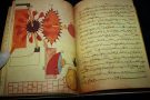
The manuscript under consideration is the Maqala fi ‘amal al-Binkam. It is extant in two copies preserved in the Süleymaniye Library in Istanbul, under the following shelf marks: Atif Efendi collection, MS 1714, item 8, folios 77r-82v and Fatih collection, MS 3439, item 8, folios 138r-140r. Extracts from both manuscript copies are produced below in figures 1 and 2.

Fig. 1. First page of Ibn al-Haytham’s Maqala fi ‘amal al-Binkam in MS Fatih 3439, folio 138r

Fig. 2. First page of Ibn al-Haytham’s Maqala fi ‘amal al-Binkam in MS Atif 1714, folio 77v.
The two copies present the same text, with significant variant readings, and they complete each other for the reconstruction of an excellent scientific text on the description, use and functions of a specific water clock, which has no other similar specimen in the Islamic tradition of technology.
The English translation of the text is based on the critical edition of the Arabic version. There were a number of challenges, which had to be met before a final acceptable English version has been reached. There was a need for not only the usual editing methodology but also for expertise in old Arabic terminology for engineering technical terms. In a number of instances we had to resort to several old texts such those by Banu Musa, Ibn Ridhwan al-Sa’ati and Al-Jazari to converge onto an acceptable meaning of a particular term. The result is a reasonable translation, which we hope will add to knowledge in this important field.
The full text of the translation is given below in an Appendix at the end of the article, at section 7.
In his description, Ibn al-Haytham gives details of the water clock. He describes it as a new invention in that it gives hours and minutes, which no other clock gave before his time. He refers to making and manufacturing as well as testing by trial and error, as well as calculations.
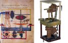
We notice that he uses a cylinder with a small hole at its base as the prime mover for telling the time. As this cylinder sinks downwards into another tank, which contains sufficient amount of water, it resembles an inflow clepsydra. This is unlike the clepsydras used of the Antiquity, which were later adapted by Muslim engineers Al-Muradi, Ibn Ridhwan al-Sa’ati and Al-Jazari, all of which were outflow clepsydras. It is interesting that Ibn al-Haytham should use this technology for the control of his clock instead of the outflow clepsydra, which should have been well known in Cairo at the time when he was in Egypt.
The sinking-bowl water clepsydra seems to have been invented in India in the early 5th century CE. Inflow clepsydras appeared in China during the Han dynasty (206 BCE-8 CE), soon after the time of Ctesibios, though there is no known connection. Tan Zheng produced inflow clepsydra that survived for a millennium, and which were drawn and described in the 11th century. Chinese engineers also struggled with the problem of keeping the flow uniform. It is therefore, possible that Ibn al-Haytham based his design on ideas coming from the East, which he acquired whilst he was in Basra. This city was an active seaport, where such technology could have reached. The Indians call the inflow clepsydra “Ghatika Yantra.”[2]
The use of the inflow clepsydra is not new but Ibn al-Haytham has used it to determine hours and minutes and designed the scale for telling the time, overcoming the problem of non-uniform motion of the sinking cylinder.
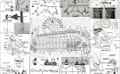
Basically the sinking cylinder is attached to a rope/string, which after passing over pulleys is connected to a shaft and a bearing onto which a circular disc is mounted. As the cylinder sinks vertically and concentrically into an outer cylindrical tank, the string rotates the disc about its own horizontal axis, see figures 3 and 4.

Fig. 3. A sketch of the clock based on the description of Ibn al-Haytham.

Fig.4. A line diagram shows the circular disc connected to the cylinder via a rope/string.
Ibn al-Haytham graduated the disc into 24 divisions that can tell the hours with subdivisions to reveal a fraction of an hour up to minutes. He calibrated each division such that one hour elapses between one division and the next. The cylinder is designed to sink in 24 hours. The marked division on the disc pass by a pointer to tell the time, see fig.5. A close up view of the divisions showing minutes is given in fig.6

Fig. 5. The upper portion of the disc passes by the pointer to indicate the time.

Fig.6. A close up view of the divisions showing, half, quarter and minutes.
The pointer is fixed separately from the disc. It is possible that the disc is placed inside a box which holds the pointer. The cylinders may be placed further away from the disc container so that the observer only sees the disc box. The string can be made sufficiently long to allow for the distance.

Fig.7. A pointer is mounted on top of the clock box. The circular disc protrudes from the top of the box. The distal end of string is connected to the cylinder, not shown in the diagram.
The calibration of the clock is thoroughly explained. Ibn al-Haytham goes through an elaborate method of calibrating the time using another one hour “Binkam” (possibly a clepsydra), with the help of two observers. By trial and error and with the use of small copper weights dropped into the inner cylinder (now used independently in another shallow outer tank, he fixes the duration of the sinking such that the cylinder hits bottom after one hour. He would also enlarge the diameter of the orifice to make it sink faster.
If however, the sinking has to be slower he suggests plugging the hole and drilling another larger hole nearby in the base. He also uses a small stopper tube at outer mouth of the hole at the bottom of the cylinder. This will stop dirt, gathered at the bottom of the outer tank from going inside the cylinder. When the cylinder is calibrated (hole diameter fixed and added weight attached), the cylinder is mounted into the big outer tank and the rope/string attached at one end to the top of the cylinder and the other to the bearing shaft of the circular disc passing around appropriate pulleys.
The marking of divisions on the circular disc is explained in a slightly confusing manner as there is reference to celestial sphere, the full celestial cycle, armillary sphere, ruler (sometimes to mean the scales on the outer periphery of the disc) and sometimes to divisions and subdivisions. The two observers used in the calibration process communicate with each other at the time when each hour is passed so that an appropriate mark is made on the disc. This then is divided into sub-divisions for parts of the hour and for minutes.
Ibn al-Haytham divides the full 360 degrees into 24 sectors, making each sector subtending 15 degrees. He takes great care in ensuring accuracy of the divisions of the hours and minutes to allow for the changes due to the slightly non-linear motion of the cylinder. He mentions that the cylinder goes faster as it goes deeper; hence the divisions become larger nearer the 24hour end. He does, however, mention that the variation is almost unrecognisable.
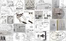
Ibn al-Haytham solved the problem of the need for the inner cylinder to move concentrically inside the outer cylindrical tank by using a framework inside which the inner cylinder slides, see Fig.8. The framework is constructed from two rings separated vertically by 4 metal vertical spacing bars to form a cylindrical frame. The rings are made from copper bars of rectangular cross section and bent and welded into a full circle. The lower identical ring is connected to 4 other bars, which radiate outwards, see Fig.10. The ends of each of these radial bars are welded to the lower ring. The distal ends of each radial bar will be welded onto the inner wall of the outer cylinder. The fixed frame now allows the inner cylinder to loosely slide and down inside the rings:

Fig.8. Method for ensuring concentric sliding motion of inner cylinder using rings and bars.

Fig. 9. The guide metal frame before welding onto the inner surface of the outer tank.
Ibn al-Haytham had to face the challenge of the need for continuous un-interrupted time by making two identical clocks resting next to each other, see Fig.10. As the first clock nears the 22nd hour, he would start the second clock synchronised with the first such that when the first one reaches 24 hours the second clock reaches the beginning of its cycle. In this way he avoids down time for resetting the clock.

Fig.10a. By using two clocks, Ibn al-Haytham was able to avoid down time for resetting the clock. The second clock is synchronised to coincide with the first clock at the latter hours.
Ibn al-Haytham does not explain how the water removed from the cylinders. He could have used the string to pull the inner cylinder out. This would require the use of the pulleys and some crank arm to winch the filled cylinder. This could be a heavy load to bear by the pulleys. There is no reference to a draining orifice in the outside cylinder. It would take too long time to drain the inner cylinder through the small orifice hole. Used for allowing the inflow. On the other hand he could have used siphons to empty both the cylinders. The latter seems the easiest and it could have been used.

Fig. 10b. 3D perspective of the clock showing all components.
The Clock in 3D Animation
All the engineering line diagrams of the clock were based on Ibn al-Haytham’s description, see Appendix. The engineering drawing drawings were then used to produce 3D animations of the clock. The animations are produced in a video film. To see it in action, press Ctrl and click on Fig.11.
Fig. 11. 3D animation video of the reconstructed model of Ibn al-Haytham’s clock. Click to see film.
The simplest mathematical model to consider is that for a cylinder of thin walled metal opened at the top and closed at the base by a circular disc. The disc has a small diameter hole at its centre. The whole is first plugged in so that when the cylinder is placed in water it sinks to a height of equilibrium. This equilibrium is reached when the buoyancy force equates the combined total weight of the cylinder and the base plate.
If the hole is unplugged the water will start filling the inner space of the cylinder and the cylinder commences to sink towards the bottom. The analysis is rudimentary and uses a simple model of the cylinder without allowing for the friction forces between the guide frame and the outer surface of the cylinder nor between the rope and the pulleys nor between the disc mounting and its axil.
The cylinder is closed by an end plate of thickness b. The cylinder is sunk initially under its own weight below the water surface. As the water goes into the cylinder through the orifice hole, the water level inside it reaches a value labelled, depth, with the surface of the water is now below the water surface outside the cylinder. The difference between the two surfaces levels is labelled, head, see Fig. 12.
Fig.12 A sketch of the model used in the mathematical analysis.
The outer cross-sectional area of the cylinder is Ao The outer diameter is Do . The cross-sectional area of the inner cylindrical space is Ai and the cross-sectional area of the wall material thickness is At . The total length of the cylinder is, len.
The list of variables and the full analysis are given in an Appendix at the end. In this analysis a practical case is chosen for evaluation.
The equations use the force balance between the weight of the cylinder and the buoyancy forces as well as the fluid flow rate through the orifice hole to predict the variation of the depth with time for the duration of 24 hours.
This paper gives a rapid examination of the clock that Ibn al-Haytham describes as being unique and “none like it before”. He actually gives an important view on all previous clocks that they do not produce accurate timings not have sufficient information on hours and minutes. Because of this shortcoming he decided to embark upon making this clock.
Both manuscripts were produced in modern Arabic fonts and then a single critical edition is produced. The full work is the subject of a separate book to be published shortly.
It is not known why Ibn al-Haytham chose to use an inflow clepsydra type instead of the out-flow type which was frequently used by the Greeks. It could be that he was in Basra when he described his clock, where Indian technology would have reached. It is also difficult to explain why Muslim engineers who came after him did not refer to this clock.
Ibn al-Haytham goes to great length to describe in detail the manufacturing method and materials of each component of the clock. He describes the calibration technique and the trails and errors of each run so that the clock can reflect time accurately in the form of hours, half hours, quarter hours and minutes.
He mentions that the cylinder sinks at a faster speed as it gains more water inside it. He allows for this by calibrating the rotating disc dial such that the spacing’s between the hour divisions become larger nearer the end of its rotation. However, he mentions that the difference is negligible.
We have attempted to produce engineering drawings of this clock and its various components based on our understanding of his description. In order to clarify its working mechanism, the clock was produced in rendered 3 D animations which were made into a video in colour.
In order to verify the workings of this clock and check that our understanding of the mechanism described by Ibn al-Haytham, we carried out a mathematical analysis of the motion of the sinking cylinder.
The parameters for the practical case chosen were fed into the analytical model. The model predicted the variation of the depth with time.
We notice that the chosen cylinder sinks almost in a uniform speed during the 24 hours period. The degree of non-linearity is small. This confirms the statements of Ibn al-Haytham.
A more sophisticated model is required. However, the governing parameters are related through equations and hence the design can easily be varied to suit different materials, sizes, etc. This then can be used to produce clock models of different sizes. For more sophisticated analysis a “Finite Element” computational fluid-solid interaction model should be built.
The English Text of Maqala fi ‘amal al-Binkam
“In the name of Allah, the Most Gracious, the Most Merciful.
May God ease this task and end it with goodness.“
The Epistle of Al-Ḥasan Ibn al-Hasan Ibn al-Haytham on the Water Clock
One of the indispensable means of telling the time, estimating the movements and calculating the parts of time is the water clocks by which the quantity of hours can be calculated. The name of such a machine is the Binkām.
Previously, many versions and types of water clocks have been made. However, all versions made of these calculate the hours or major parts of the hour. Each equinoctial hour,[3] which can be calculated using the Binkām, is divided into fifteen parts from the parts of the motions of the <celestial> sphere. I mean that when fifteen parts of the circle of the celestial equator are on the circle of the meridian, this duration is called an equinoctial hour. It is this type of hour which can be determined using the Binkām.
All such machines are used to calculate hours consisting of fifteen parts of time. Some types are used to calculate <smaller> parts of an hour which are halves, thirds, quarters and other similar fractions. Not all water clocks can calculate parts of an hour, which is equal to the degrees of the <celestial> sphere. I mean that according to the findings and results <up to our time>, <these> machines do not calculate the fifteen parts which each cycle consists of, or the minutes of each part which are equal to the minutes of the parts of the <celestial> sphere.
Because of this situation, we decided to endeavour making a clock comprising of a cylinder immersed in water to indicate the time elapsed part by part, and by which each cycle of the <celestial> sphere consists of three hundred and sixty parts.
In addition, it is also used to calculate the number of minutes that have elapsed in each part consisting of sixty minutes. We are not aware of any other water clock, which can tell the degrees and minutes <in this manner>. This clock is superior in many ways, in particular for the nocturnal ascensions. Nocturnal ascensions can be observed accurately using this machine only.
In most cases, nocturnal ascensions occur when the fixed planets rise. However, the locations of fixed planets are not certain; this is why the scholars of this art disagree about their movements. When this machine is set up after sunset until the needed time of the ascendant and the time that is calculated by this machine elapses, this calculated duration is the revolved portion of the sphere, from sunset till the needed time of the ascendant, in minutes. If it is calculated at that time, the ascendant’s part is calculated in minutes. When we set up the machine at the time of the needed ascendant and a fixed planet is chosen and observed till it reaches the circle of the meridian, and when the time in the Binkām – I mean this clock – elapses, then this calculated time is most accurate. The ascendant calculated during this period is calculated in minutes, as the sun’s location can be observed from the circle of the ecliptic[4] using this machine.
If the longitude of the sun is observed at noon one day and should be observed at the same time on the following day, and the longitude of the meridian is located on the horizon, a gnomon is erected on the line waiting till the shadow of the gnomon is on the longitude of the meridian on the day which the longitude of the sun is observed, then this machine –I mean the Bunkum – is set up immediately and is observed till the <celestial> sphere completes a full cycle <24 hours>.
This is done by setting up two Binkāms in the manner we shall describe, the first one is set up then it is followed by the second. I mean that once the first one is half full, the second one is set up immediately and when the second one is full the first one is set up in the same way. This continues till the <celestial> sphere completes a full cycle, which is three hundred and sixty parts of the full duration.
At this stage, the sun will not have returned to the circle of the meridian because it will have moved in its course from West to East. The sun only reaches the circle of the meridian after the <celestial> sphere competes a full cycle in addition to the ascensions of what the sun moves in its circle from when the sun is at the circle of the meridian on the first day till its return to that position the following day. When the sun is observed using this Binkām, we start setting up the Binkām when the sun is at the circle of the meridian on the first day for which the sun’s longitude was observed at noon. The Binkām is observed and replaced till the sun returns to the circle of the meridian on the following day, and the time the Binkām calculates is recorded. If slightly more than a complete cycle of time has elapsed, a full cycle of three hundred and sixty equal parts is subtracted and the remaining minutes are calculated and added to the table of ascensions of the right sphere. A similar amount regarding the sun’s position from the first day till the following day is taken from the table of ascensions.
Then we search what corresponds to it from the parts of the zodiacal circle. If the minute corresponding to the parts of these ascensions is the same minute in which the sun’s longitude is observed at noon of the second day, then the sun’s position is located correctly. If what corresponds to these ascendants is a minute other than the minute in which the sun’s longitude is observed at noon, then the sun’s location is not certain, if the calculation of the sun’s longitude, the machine’s settings or the observations were carefully operated.
In addition, the location of moving/wandering planets can be found using this machine. This machine has a significant role in the art of astrology. Now that this has been clarified, let’s proceed in explaining how this machine functions.
A copper cylindrical machine is used; its length should be one arm and four fingers and the diameter of its base a quarter of an arm (i.e. six fingers). It should be perfectly rounded, isomorphous. We take a round and isomorphous plane piece of copper, thick and equal to the size of the cylinder’s base. It is welded onto one of the cylinder’s ends. Its edge is rasped so that it fits perfectly onto the cylinder. A fine hole, as small as a needle’s, is marked and pierced in the middle of the base, and then a cylindrically shaped copper tank is brought. Its length should be similar to the first cylinder’s length and the diameter of its base should be no less than half an arm (i.e. twelve fingers). The body and base of the tank should be thick enough. Underneath it, poles are placed to carry it and keep it off the ground. The poles should be <like> squared teeth to prevent it from sinking into the earth. On its sides, two loops are attached to help carry it when needed.
Then, two round copper rings with square surfaces are brought. The capacity of the rings should be enough to allow the small cylinder to be placed inside them. Both the cylinder and the rings should be able to be moved smoothly. The width of each ring should be one finger and the thickness of each one also one finger. Both rings are attached with a lathe onto the vessel,[5] shaping each one into a circle inside one of its opposite surfaces.
The thickness of the ring is reduced till the surface becomes narrower than the opposite surface that has just been prepared. This is done so that when the cylinder is placed inside the ring, it is placed in one circular line allowing the cylinder to move easily inside the ring. When both rings are prepared, eight copper bars are brought; four of which are small and four of which are large. The length of each of the small bars should be equal to half the distance between the diameter of the vessel’s capacity (i.e. the large cylinder) and the diameter of the inner periphery of each of the rings. The length of each of the large bars should be more than the small bars’ by half an arm. The width of all the bars should be a finger and a half and their thickness half a finger.
All of them are prepared and when ready, the four small bars are welded onto the quarters of one of the rings. Two bars are fixed onto the sides of one the ring’s diameters. The remaining two bars are fixed onto the sides of the other diameter crossing the first with right angles. A hole is made in each bar, in which the ends of each bar are inserted and preferably welded. The large bars are fixed onto the other ring in the same manner. Once done, the ring is securely placed on top of the first ring and the large bars are placed on top of the small bars. The inner periphery of the ring is prepared similarly to the first ring’s inner periphery. Marks are written on the large bars where the edges of the small bars are, and then the large bars are bent at those marks.
It is always the large bars that are bent at the edges of the small bars. When the large bars are bent, the ring with small bars is fixed onto the vessel (i.e. the large cylinder) and its edge is welded on the vessel’s periphery. Preferably, holes should be made on the vessel’s periphery where the ends of the bars are placed, and the ends of the bars should be inserted, preferably welded, in them so that its periphery is similar to the vessel’s periphery. The large bars are fixed onto the vessel. The vessel is inserted inside these bars (i.e. the large ones) that surround the vessel, because the distance between each opposite pair of bars is equal to the diameter of the vessel’s capacity. The bars are welded around the vessel’s periphery and at the middle sections of the vessel’s quarters, which were created using the small bars. It is then welded firmly.
Preferably, it should be nailed then welded. When the bars are attached to the vessel, the rings become opposite each other. Before welding the bars, the user should ensure that the small cylinder is put inside the rings and moved till the higher ring is placed opposite the lower ring. This can be done by observing the cylinder’s movement in the rings, ensuring that it is moving smoothly without difficulty. Once done, the bars are nailed onto the vessel and the cylinder nailed inside the rings, then both are welded. This ring is used in order to hold the small cylinder when it rises towards the large cylinder and to keep it upright, preventing it from leaning to one side or the other.
When completed, another bar made out of copper is brought. Its length should be one arm and two fingers, its width less than two fingers and its thickness a quarter of a finger. It should have straight sides. The bar is then shaped into a concave shape and hammered till its surface is cylindrical. Its surface should be as concave as the small cylinder’s surface is convex. The cylinder’s shape is estimated and hammered till its surface can be securely placed on top of the cylinder’s surface.
When this is done, the bar’s margins are prepared and two opposite holes are made in the parallel rings. The width of each one should be equal to the width of the concave bar and the thickness of each one is equal to the bar’s thickness. Both rings are adjusted in a manner that allows the bar to be inserted in them when necessary and after that removed. The hole made in the lower ring should be at the end of one of the small bars.
When these two holes are prepared, the bar is attached onto the rings and a mark is made on the back of the bar at the surface of the higher ring. The bar is then taken out of the hole and the mark is pierced. Inside it, a small square cuboid shaped one finger long and two units wide stud, with prepared margins, is put. The stud is put in the hole in the bar and is welded firmly. The bar is then fixed onto the rings and the stud is applied and secured on the surface of the higher hoop. A mark is made where the position of the stud is and the bar is elevated.
On the mark that was made on the ring’s surface, a small hole similar to a loop is made so the stud can be put in it. It should be put inside it with force, preventing the bar form moving when inserted. When the loop is adjusted it is welded to the ring. When completed, the bar’s inner concave surface is prepared and the bar is prepared and released. When this is done, the machine is now complete and only its division and calibration remain.
It is calibrated by using a previously calibrated one-hour clepsydra. By using this calibrated hour, we calibrate the functioning this Binkām set up by using another outer tank with shallower water. This tank is set up by having clear water poured into the vessel, filling it almost completely <the outer vessel, calibrated tank, is filled with water enough only for one hour>. Then, the small cylinder is inserted in the rings till its base is in the water. The calibrated one hour Binkām is filled with water and the cylinder is placed inside it and both are observed. The observer carries small pieces of copper and waits till an hour of time in the calibrated Binkām elapses.
When an hour elapses in the calibrated Binkām, the observer checks the cylindrical machine. If it has sunk into the water and if its base has settled on the base of the vessel, then the aim has been achieved. If it has not totally sunk down but has almost reached the base, the observer throws one piece after the other of the small prepared copper pieces at a time into the cylinder till it totally sinks. When it sinks, the machine is emptied and the copper is taken and smelted into a ring and is used to encircle the cylinder from the inside. It is then welded and calibrated till it sinks during the parts of one whole hour. If the cylinder is calibrated and a whole hour has elapsed in the calibrated Binkām yet a lot remains in the cylinder, the cylinder is emptied and the hole in its base is widened. It is then calibrated again and again till the cylinder completely sinks during the parts of one whole hour and till a small amount remains.
Then, pieces of copper are dropped inside it and are shaped into a ring that is used to encircle the inner surface of the cylinder. If the cylinder sinks before an hour has elapsed, it is emptied and the hole in its base is shut. Another hole, narrower than the first hole, is pierced in its base. It is then calibrated again till the cylinder completely sinks to the base of the vessel at the end of one whole hour. When this happens, the machine is emptied.
You use a piece of onyx or garnet or any other similar type of adamant. It is then drilled with the same drill used on the base of the cylinder. A layer of copper is brought to cover the stone and surround it completely. The layer of copper is prepared from all sides and the stone is inserted in it. Asphalt or tar is used to stick them together. The stone is then attached to the outer surface of the cylinder’s base. A fine needle is inserted in the hole in the stone and is used to pierce the cylinder’s base. The needle passes through both holes and is then attached to them. The layer is then welded onto the base after which the needle is taken out. At this stage, the machine is complete, leaving only its division.
The machine is divided using an armillary sphere. The appropriate oval armillary sphere is set up and its pole is elevated. It should be the type of armillary spheres, which are divided into minutes or parts smaller than the degrees. The machine is set up and placed next to the armillary sphere in a house or a shaded location, protecting it from wind or dust. The vessel is filled with clear water and the curved ruler is put inside the two rings. The cylinder is inserted inside the ring and a person remains to observe it, carrying a quill pen and inkbottle while another person observes the armillary sphere.
Whilst keeping an eye on one of the large fixed planets, he turns the disc till he sees the planet from the holes in the two layers. Between the two layers a tube is placed. Another person is asked to watch the armillary sphere and observe the circle of the celestial equator in the armillary sphere. The person observing the planet turns the disc, till the end of a part of the celestial equator becomes the surface of the circle of the meridian. When this is prepared, the person observing the circle of the celestial equator is addressed. If he answers, the person observing the Binkām draws a line with the quill pen on the curved ruler around the disc’s periphery. Then the person observing the planet is addressed and he turns the armillary sphere till one part of the circle of the celestial equator turns. If the part finishes at the circle of the meridian’s surface, the observer of the circle of the celestial equator is addressed. If he answers, the observer of the Binkām draws a line on the ruler. This continues till fifteen parts of the circle of the celestial equator, which are equal to an equinoctial hour, have turned. If fifteen parts of the disc have turned, the cylinder will have sunk. If it has not, then either the experiment with the Binkām is incorrect, or the calibrated Binkām used is inaccurate or the experiment with the armillary sphere was not prepared properly. If this occurs, another Binkām, other than the first, is used and the machine is calibrated with it and the armillary sphere is experimented with. The armillary sphere should be prepared in a manner, which allows the machine to sink in water after fifteen parts of time have elapsed. If fifteen parts of time have elapsed and the armillary sphere is prepared and used properly yet the machine has still not sunk, one small piece of copper at a time is dropped till it sinks and erases the lines drawn on the ruler.
The cylinder is then emptied and the cooper inside it is taken out and made into a ring used to encircle the inner part of the cylinder. It is then experimented with till it sinks after fifteen parts of time have elapsed since its preparation and release. If it sinks before fifteen parts of time have elapsed, its periphery is rasped with a rasp and reduced. It is then experimented with till it sinks after fifteen times segment has elapsed from the full cycle <360 time segments> circle of the celestial equator. When this calibration is prepared and set, both the machine and the armillary sphere are set up and the parts of the celestial equator are experimented with. The observer should be alert while observing it and draws a line in the curved ruler after each part of time has elapsed, till the bar is divided into fifteen parts and has fifteen vertical lines. When the division of this ruler is done, three tables are drawn on the bar’s length; one in the middle and two on its sides. The lines are drawn using iron and should be clear. The three tables are then horizontally divided into fifteen parts where the marks were made. Each part of the middle table is then divided into sixty equal parts. These parts can be divided into sixty parts because they are spacious parts, as when added together, they are equal to a complete arm’s length, and all the parts together equal nine hundred parts and it is not difficult to divide an arm’s length into nine hundred parts.
If the owner of this machine would like the small parts to be wider, the length of the cylinder and the ruler should be increased and the orifice hole pierced in the cylinder’s base should be widened, and then he can do so. After each part is divided into sixty small divisions, a line is drawn at the end of every five divisions. This line crosses one of the marks on the side of the middle table, dividing each part into six; each division equalling five minutes. In each division of the mark (i.e. of the fifteen divisions) the numbers “five” and “ten” are written consecutively till sixty is reached. In the parts of the remaining divisions on the other side, numbers one to fifteen are written starting from the top of the ruler.
The writing is made with iron and should be clear so that it stays and remains. Once this division is complete, the making of the Binkām is complete. When this Binkām is set up and observed, it tells the duration of time that has elapsed, minute by minute and part by part. With regards to the parts, it is clear that their division is most accurate. The parts of the ruler (i.e. the fifteen parts) do not have to be equal because the heavier the Binkām is, the faster it sinks in water. Therefore, the first part of the ruler should be the smallest and is followed by a larger division, which is followed by a larger division and so on. So, the length of the parts increases gradually making the last part the longest. However, the increase in length between them should not vary. On the other hand, each of the sixty parts varies; however this variation which cannot be sensed, seen or felt. Therefore, we made these parts equal because dividing them equally is enough for realising the minutes of the parts by the senses. This is what we explained is the making of the Binkām which reveals the minutes of the parts of time. This was the objective of this essay.
The essay on the Binkām is now complete. Praise be to Allah, Lord of the two worlds and may His Blessings be bestowed upon His Messenger Muḥammad and all his family.
[1] For more details on Ibn al-Haytham’s life and works, see Abdel Hamid I. Sabra, Ibn al-Haytham: Brief life of an Arab mathematician: died circa 1040, Harvard Magazine, September-October 2003 and A. I. Sabra, “Ibn Al-Haytham, Abu ‘Ali Alhasan Ibn Al-Hasan.” Complete Dictionary of Scientific Biography. 2008. Retrieved November 19, 2013 from Encyclopedia.com: https://www.encyclopedia.com/doc/1G2-2830905785.html.
[2] See Ancient Indian Leaps into Mathematics, edited by B. S. Yadav and Man Mohan, Basel: Birkhauser Verlag, 2010, p. 104.
[3] Sa’a mustawiya: literally “equal hour”, but this is a technical term of spherical astronomy translated usually in the specialised literature by “equinoctial hours” contained in one day, obtained by dividing the day arc by 15 degrees. See Mohammad Bagheri, “Kushyar Ibn Labban’s Glossary of Astronomy,” SCIAMVS, vol. 7 (2006): pp. 145-174; p. 154.
[4] Dā’irat falak al-Burūj: Literally circle of the zodiacal signs, but its technical meaning is the “Circle of the ecliptic, which is the circle described by the sun through its proper motion from west to east, during a single rotation in each> year. See M. Bagheri, “Kushyar Ibn Labban’s Glossary of Astronomy,” SCIAMVS, vol. 7 (2006): pp. 145-174; p. 149.
[5] The word is not clear in the two manuscripts, reading respectively “sahr or sahd” in MS Atif 1714 and “shahr” in MS Fatih 3439. The context of the phrase refers to the main vessel called by the author “Quds”.
Discover the golden
age of Muslim civilisation.
© Copyright FSTC Ltd 2002-2020. All Rights Reserved.