![]()
The SmartPAK / xPOD Radiant Energy Management System
UPDATED: January 25, 2006
SmartPAK is the world's first all solid-state Radiant Energy Management System that collects radiant energy as excess electrical energy. It provides a "standard" platform for experimenters, researchers, and developers to do energy-related practical applications, experiments, and perform exploration of the Radiant Energy phenomena. The theory of operation is based on the difference of energy between magnetization / demagnetization cycles of a transformer / Perreault Valve Head Assembly, which is called an xPOD Head Assembly. It has been discovered EXCESS energy is released during the demagnetization portion of the cycle using a suitable xPOD Head Assembly. The SmartPAK system is specially designed to measure, collect, and store this excess energy for later use.
The SmartPAK system is controlled by a Freescale 68HC908AB32 microcontroller programmed to measure input / output voltages and currents, calculate COP and Delta Power, and contains software algorithms for a complete "turn-key" energy management system. The system features a "standard" user interface, which allows the user to design their own custom "xPOD Head Assemblies", and immediately test and display in real-time its' performance.
Figure 1 shows a complete SmartPAK Radiant Management System.

Figure 1. The SmartPAK P1210 Radiant Energy Management System.
Figure 2 shows how SmartPAK calculates COP and Delta Power. The average input / output voltages and currents are measured to / from the xPOD Head Assembly. These voltages and currents are read in real-time by the microcontroller, and COP and Delta Power are calculated and displayed on an LCD screen. The charging / discharging status of the batteries are continuously monitored.

Figure 2. An overview of the SmartPAK / xPOD System.
Figure 3 shows the "heart" of the SmartPAK system. The 68HC908AB32 microcontroller chip is shown in the lower left hand corner of the photo.
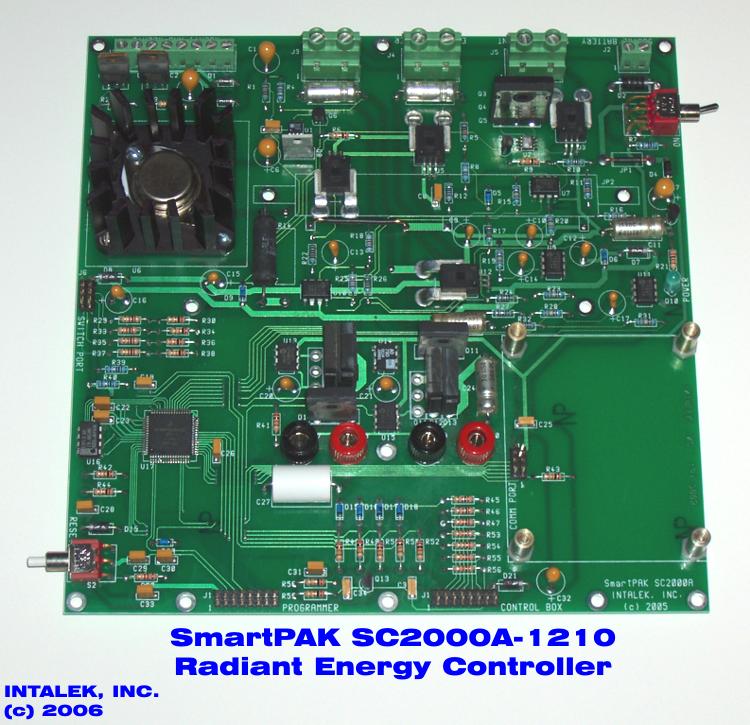
Figure 3. The new SC2000A-1210 fully populated SmartPAK Controller.
Figure 4 shows the functional block diagram of the SmartPAK system. A key feature is the double battery arrangement, where the first battery powers the load and the controller, and the second battery is being charged. The charging and discharging state of both batteries are continuously monitored by the microcontroller.
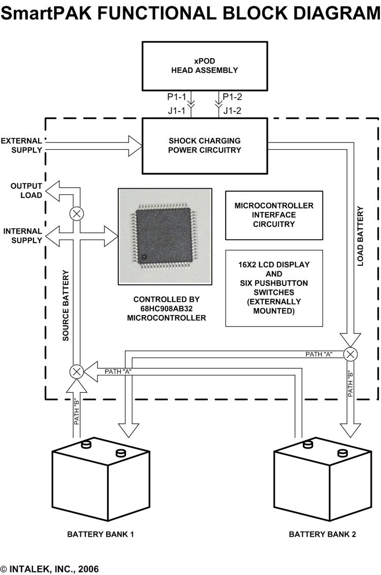
Figure 4. The functional block diagram of the SmartPAK / xPOD System.
![]()
The xPOD Head Assembly
Using The Perreault Valve
In the SmartPAK system, the xPOD Head Assembly contains a transformer / valve arrangement that is cyclically magnetized and demagnetized. During time t < 0 seconds, the transformer is magnetized. The secondary side voltage of the transformer is sufficiently high such that it doesn't exceed the breakdown voltage of the valve. During time t >= 0 seconds, the transformer is demagnetized. The secondary side voltage of the transformer reverses as an impulse function due to a Lenz's Law reaction. This impulse function will exceed the breakdown voltage of the valve causing an "electric" spark to flow across the valve. This releases Radiant Energy, and this energy is collected as EXCESS "electric" energy. This excess energy is transferred back through T1, as T1 demagnetizes.

Figure 5. The Perreault Valve.

Figure 6. The Perreault Valves.
Figure 7 shows two types of xPOD Head Assemblies. The top diagram shows the closed flux path version, which is the preferred method because the magnetic flux is contained or trapped entirely within the magnetic media of T1. Magnetic interference is therefore minimized and restricted to the valve. The transformer / valve assembly is contained within a magnetically shielded box.

Figure 7. Two types of xPOD Head Assemblies.
Figure 8 shows how to harvest excess "electric" energy from the Perreault Valve. During the magnetization phase, a voltage is applied to the primary side of T1 from Battery 1 (BAT1) as shown in Figure 2 by closing Switch S1. A high voltage appears on the secondary side of T1. This voltage doesn't exceed the breakdown voltage of the valve, therefore, no current flows through the valve. During the demagnetization phase, the magnetization current flowing through the primary side of T1 is quickly shutoff by opening Switch S1. This causes the voltage on the primary side to suddenly reverse and produce an impulse function due to Lenz's Law reaction. A sudden change in flux also produces a voltage reversal and an impulse function on the secondary side. This voltage reversal exceeds the breakdown voltage of the valve causing a spark to jump through the valve. This spark releases Radiant Energy, hence, excess "electric" current flows out of the valve and into the secondary side of T1. This excess "electric" energy is then transferred to the primary side of T1, which charges up Battery 2 (BAT2) as shown in Figure 2.

Figure 8. Harvesting excess energy from the Perreault Valve.
![]()
Typical SmartPAK Application: The eBike Electric Bike

Figure 9. The eBike powered by SmartPAK.
![]()
MORE INFORMATION
![]()